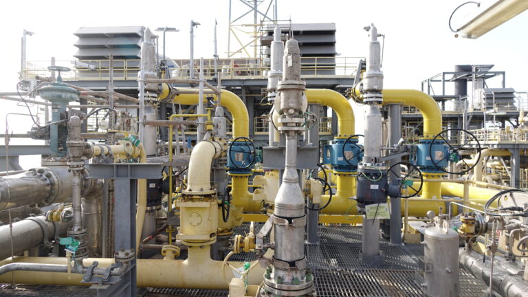
The diagnosis was performed on the whole package, including the motor, the gear & the compressor, and also on the attached pipework. Measurements were performed at various loads, knowing that SBM had decided to operate the flash gas compressor below its nominal speed to lower the vibrations.
Screw Compressor Vibration Diagnosis
Context & Issue
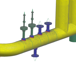
SBM Offshore was facing vibration issues onboard an FPSO provoked by the Flash Gas Compressors installed within the vessel. High vibrations were identified on the process pipes leading to loosening &/or failure of several instruments mounted on the pipes.
![]()
Client benefits
01
Reactivity
2 senior engineers involved in the offshore mission within a couple of weeks
02
Proactivity
Proactive attitude to refine the strategy while measurements were still ongoing
03
Solutions
Recommendation to avoid further failure when leaving the vessel
04
Mitigation
Support from simulation team to understand the root cause and propose mitigation
Key Development Points
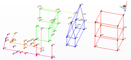
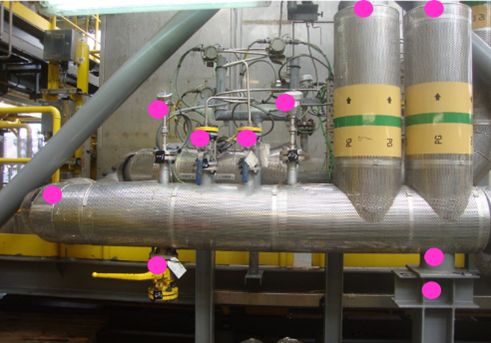
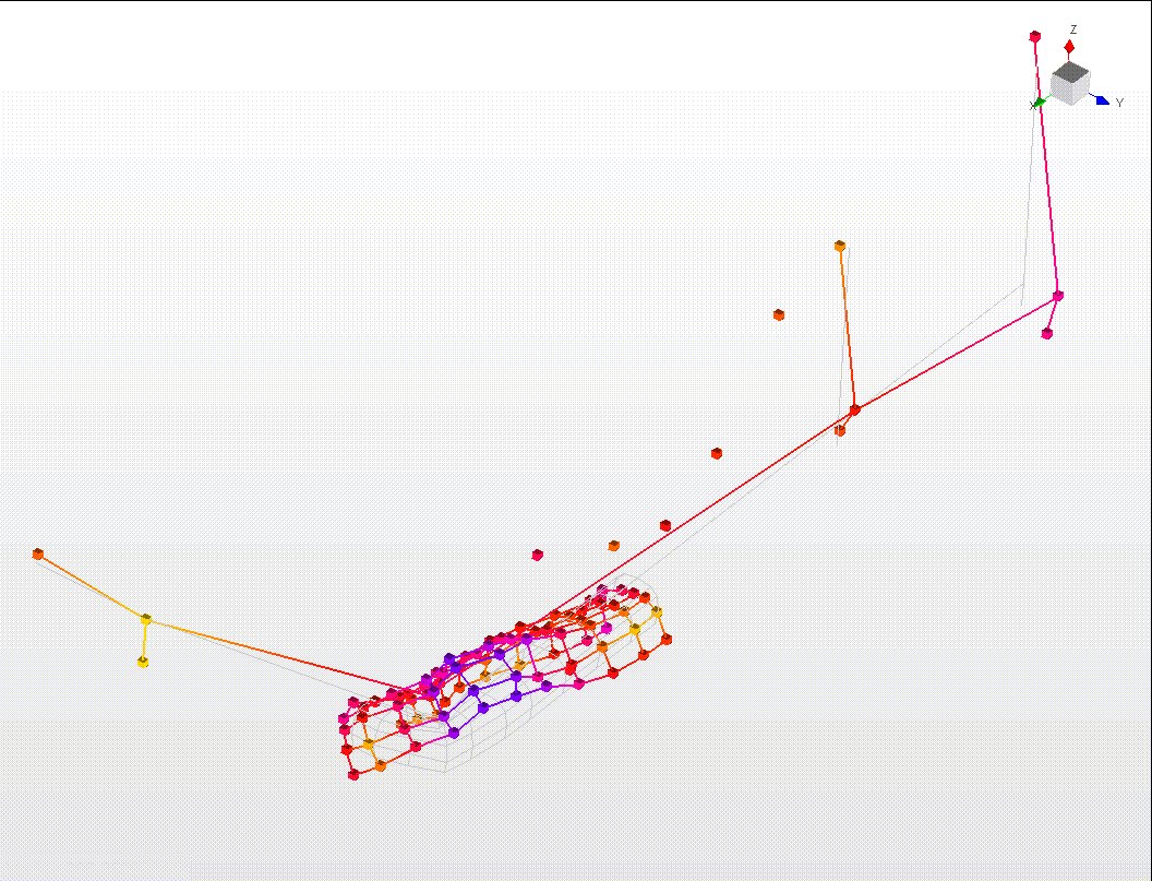
Measurement mesh
Criteria used to control the equipment depend on their type:
- ISO 20816-3 for the motor
- API 613 for the gearbox
- API 619 for the compressor
- Energy Institute guidelines for the piping (1st stage discharge pipe)
Vibration levels
Measured values demonstrated that the levels were acceptable or not too critical on the motor, the gear and the compressor, but were extremely high on the First stage discharge line. This preliminary status explains the failure observed on this line, and also indicates that the levels are not due to a mechanical transmission of the vibration from the Flash gas compressor to the pipe work.
What cause ?
Many causes could explain the high vibrations on the 1st stage discharge pipe.
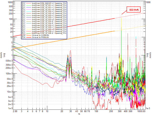
The high levels occured at 322 Hz, which corresponds to the pocket pass-by frequency. Pulsation measurements pointed out that the pulsation upstream the silencer was far too high, which can have 2 origins:
- Unproper behavior of the compressor, even if the vibration levels remain acceptable.
- Silencer inefficiency.
Certain causes were excluded based on the measurement analysis:
- Pipe supports are efficient.
- Piping bending modes, usually involved in Small Bore failure, did not explain the vibrations, because they were much lower than 322 Hz. This frequency is more associated with piping shell modes.
At the end of the mission, the understanding of the failure was partial:
- The pulsation was abnormally high in the 1st stage discharge line, and further verification was recommended, more specifically regarding the silencer and the compressor.
- The vibration levels could not be explained only by the excitation; the mechanical response must be involved to a certain extent, even if it had not been clearly identified.
It was recommended to avoid a specific regime where pulsation reached their maximum levels.
Root cause analysis
Back in Vibratec offices, additional analyses were engaged: to complete the preliminary analysis and define appropriate mitigation, a Finite Element Model of the line was built.
Strategy
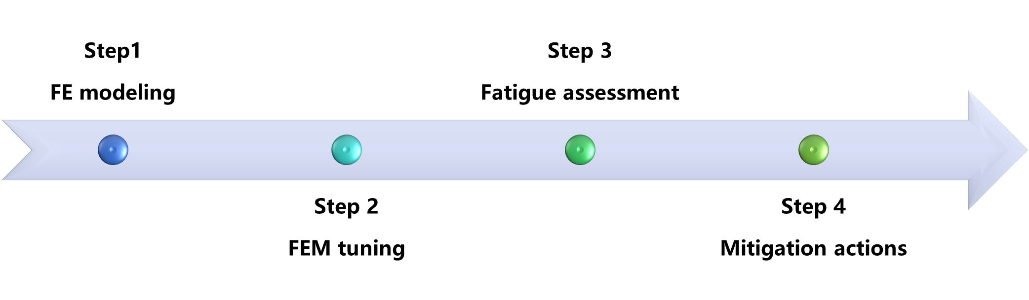
Tuned model
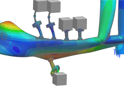
Once the model was built and tuned with the measurements, it was possible to identify the presence of a pipe shell mode at 322 Hz, matching the compressor pocket passing frequency.
Fatigue assessment
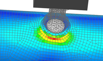
Stress computed at the Small Bore welding was above the fatigue limit and definitively explained the failure on the line. It became possible to search for mitigation.
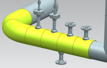
Mitigation
The strategy In a case of resonance is to avoid coincidences between the excitation frequency and the mode frequency. As it was not possible to modify the pocket passing frequency, the only solution was to shift the piping shell mode.
Two solutions were proposed:
- Use a thicker pipe to increase the wall thickness. This solution is theoretically simple, but not that practical to implement, as it implies replacing a significant portion of the pipe and completely interrupting the compressor.
- Install reinforcing wraps to locally increase the pipe wall stiffness, without dismantling the discharge line.
Either solution would reduce vibration levels by a ratio 10, from more than 100 mm/s to less than 12 mm/s.
 *
*
Piping vibration diagnosis
Instrumentation, Simulation, Analysis
Our expertise to serve your projects
Want to know more?
Contact us


Root cause analysis
Back in Vibratec offices, additional analyses were engaged: to complete the preliminary analysis and define appropriate mitigation, a Finite Element Model of the line was built. The strategy is presented in the following figure.
Once the model was built and tuned with the measurements, it was possible to identify the presence of a pipe shell mode at 322 Hz, matching the compressor pocket passing frequency.
Define mitigation
The strategy In a case of resonance is to avoid coincidences between the excitation frequency and the mode frequency. As it was not possible to modify the pocket passing frequency, the only solution was to shift the piping shell mode.
Two solutions were proposed:
- Use a thicker pipe to increase the wall thickness. This solution is theoretically simple, but not that practical to implement, as it implies replacing a significant portion of the pipe and completely interrupting the compressor.
- Install reinforcing wraps to locally increase the pipe wall stiffness, without dismantling the discharge line.
Either solution would reduce vibration levels by a ratio 10, from more than 100 mm/s to less than 12 mm/s.
