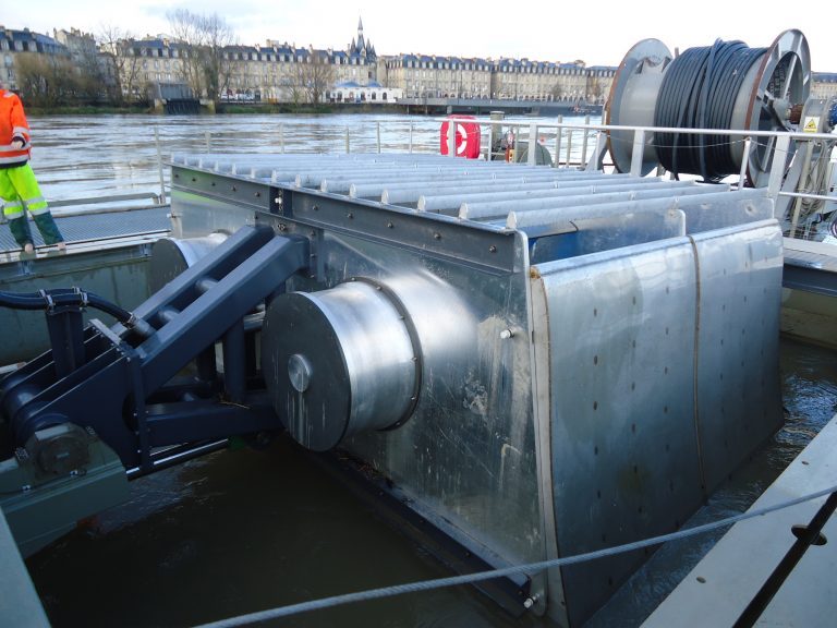
Sirech Hostier wanted to validate the design of a new RH605-1 tank by calculation as part of its development.

Computational validation of reservoir design prior to production
Context & Issue
Challenges
01
Security
User and environmental safety were key issues. The tank had to be designed to withstand the pressures and forces applied to it, to prevent leaks, explosions and structural failure.
02
Reliability
The reservoir must be able to operate reliably and consistently under variable conditions such as temperature, pressure, corrosion, etc.
03
Cost
Computational validation can reduce design costs by reducing the number of physical prototypes required and enabling faster design iterations.
04
Compliance
Standards and regulations vary from country to country, and safety and quality requirements can be stringent. Validation by calculation ensures compliance with local and international requirements.
Key Development Points
Modal analysis of the reservoir
Modal analysis is a structural analysis technique used to determine an object’s natural frequencies and vibration modes. This analysis is useful in the design of tanks and other structures, as it ensures that the structure will not vibrate excessively or dangerously under dynamic loads.
Here are the general steps involved in modal analysis of a tank:
- Modeling the tank geometry: First, the tank must be modeled numerically using simulation software. The reservoir geometry is represented using finite elements, which are simply shaped elements (such as triangles or quadrilaterals) that are assembled to form a numerical representation of the structure.
- Definition of boundary conditions: Next, the boundary conditions are defined. These include attachment conditions (which fix the reservoir in space), load conditions (which represent the forces acting on the reservoir) and fluid conditions (which represent interactions with the liquid or gas contained in the reservoir).
- Calculating natural frequencies: Once the model has been created and the boundary conditions defined, the natural frequencies of the reservoir could be calculated. These frequencies represent the structure’s natural modes of vibration, i.e. the vibrations that would occur if the structure were excited without any external source of vibration.
- Vibration mode analysis: Vibration modes are represented as vectors indicating the directions and amplitudes of displacement of the structure for each natural frequency. Vibration mode analysis helps us to understand how the reservoir will vibrate under the effect of different external vibration sources.
- Design verification: Finally, the modal analysis results were used to verify the design of the reservoir. If it’s natural frequencies fall within the frequency ranges of potential external vibrations, vibration problems may occur. In this case, design modifications may be necessary to reduce vibrations and ensure the safety and reliability of the structure.
Static analysis
Static analysis is another structural analysis technique that determines deformations and stresses in an object under static loads (i.e. loads that do not vary with time). This analysis is also useful in the design of tanks and other structures, as it ensures that the structure will not undergo excessive deformation or stress under the effect of static loads.
Here are the general steps involved in the static analysis of a reservoir:
- Reservoir geometry modeling: As with modal analysis, the reservoir must be modeled numerically using simulation software. The reservoir geometry is represented using finite elements, which are assembled to form a digital representation of the structure.
- Definition of boundary conditions: The reservoir’s boundary conditions must be defined. This includes fixing conditions, load conditions and fluid conditions.
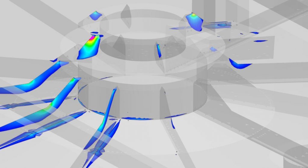
- Calculation of deformations: Once the model has been created and the boundary conditions defined, the deformations of the reservoir can be calculated. Deformations represent changes in the shape of the structure under static loads.
- Stress calculation: Stresses in the reservoir can also be calculated from deformations. Stresses represent the internal forces created in the structure in response to static loads.
- Design verification: The results of the static analysis can be used to verify the reservoir design. If deformations or stresses in the reservoir are too high, design modifications may be necessary to reinforce the structure and guarantee its safety and reliability.
Dynamic response analysis
Dynamic response analysis is a structural analysis technique used to determine the response of a structure under dynamic loads, i.e. loads that vary with time. This analysis is also useful in the design of reservoirs and other structures, as it ensures that the structure will not undergo excessive deformation or stress under the effect of dynamic loads such as earthquakes, waves or wind.
Here are the general steps in the dynamic response analysis of a reservoir:
- Reservoir geometry modeling: As with modal and static analyses, the reservoir must be modeled numerically using simulation software. The reservoir geometry is represented using finite elements, which are assembled to form a digital representation of the structure.
- Definition of boundary conditions: Boundary conditions must be defined. These include fixing conditions, load conditions and fluid conditions.
- Definition of dynamic loads: The dynamic loads affecting the reservoir must be defined. These loads may include earthquakes, waves or wind. Loads are usually represented as time-varying force functions.
- Dynamic response calculation: Once the model has been created, boundary conditions defined and dynamic loads specified, the reservoir’s dynamic response can be calculated. Dynamic response is the response of the structure to dynamic loads, and can include deformations, stresses and reactions of the structure.
- Design verification: The results of the dynamic response analysis can be used to verify the reservoir design. If deformations or stresses in the reservoir are too high under dynamic loads, design modifications may be necessary to reinforce the structure and ensure structural safety and reliability.
Detailed fatigue analysis
Fatigue analysis is a technique used to predict the service life of a component as a function of the cyclic loading it undergoes. In the case of tanks and reservoirs, fatigue analysis is important because this equipment is often subjected to cyclic loads such as internal pressures, temperature variations or movements of the contained fluid.
Here are the general steps involved in fatigue analysis of a tank:
- Determining cyclic loads: The first step is to determine the cyclic loads to which the tank is subjected. These may include internal pressures, temperature variations, movements of the contained fluid or vibrations.
- Defining load cycles: Cyclic loads must be defined in terms of load cycles. A load cycle is a sequence of loads repeated over time. For example, a load cycle for a tank can be defined as a sequence of internal pressures that vary over time.
- Numerical tank modeling: The reservoir must be modeled numerically using simulation software. The reservoir geometry is represented using finite elements, which are assembled to form a digital representation of the structure.
- Calculation of local stress: For each load cycle, the local stress must be calculated. The local stress is the maximum stress experienced by the reservoir material during the load cycle. It is calculated from the results of the numerical simulation.
- Service life assessment: Based on the local stresses calculated for each load cycle, the service life of the tank can be estimated using fatigue models. These models take into account the mechanical properties of the tank material, as well as the cyclic stresses experienced by the tank.
- Design verification: The results of the fatigue analysis can be used to verify the tank design. If the estimated service life is less than the desired service life, design modifications may be necessary to strengthen the structure and guarantee its reliability over time.
Results & Benefits
- Full-skin stresses resulting from static or dynamic loading are below the material’s fatigue. The structure is adequately designed and should be able to withstand cyclic loading throughout its expected service life.
- Fatigue analysis of the most sensitive weld seams indicates an infinite service life in these areas. It will still be important to carry out regular inspection of the weld joints to ensure that they show no signs of degradation or defects that could affect their service life.
- Tank design was validated. It remains advisable to follow good design, manufacturing, inspection and maintenance practices to ensure that the structure is sufficiently robust and reliable for its intended function.