
Accelerometer instrumentation
Instrumenting a motorized fan involves measuring several key parameters, such as rotation speed, air pressure, temperature and vibration. Here are the general steps involved in instrumenting a motorized fan:
- Planning: before instrumenting the motorized fan, it’s important to plan the measurement points according to the parameters you wish to monitor. In general, measurement points should be strategically located to ensure accurate measurement of the desired parameters. For example, temperature sensors can be placed at the fan inlet and outlet, and vibration sensors can be placed on the motor housing and fan support.
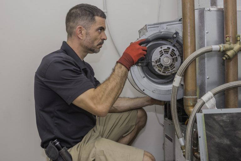
- Sensor installation: once the measurement points are determined, the sensors can be installed. Speed sensors can be installed using proximity or Hall sensors, while air pressure sensors can be installed using differential pressure sensors. Temperature sensors can be installed using thermocouples or resistance temperature sensors. Vibration sensors can be installed using accelerometers.
- Measurement interface configuration: once the sensors are installed, a measurement interface can be configured to collect and display the data collected by the sensors. Modern measurement interfaces can be programmed to display data in real time and save the collected data for later analysis.
- Verification and calibration: before starting to collect data, it is important to confirm that the sensors are correctly installed and calibrated to ensure accurate measurement of the desired parameters.
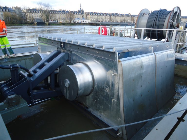
Operating measurements (steady-state and ramp-up)
Performing measurements during operation is important for obtaining accurate data representative of actual motor-fan operation. This makes it possible to detect variations in operating conditions and fluctuations in performance parameters, which may differ from those obtained when measuring at standstill.
Here are some important considerations to bear in mind when carrying out measurements during operation:
- Safety: before carrying out measurements in operation, it is important to take safety measures to protect operators and equipment. This may include disabling safety systems, using sensor protection, and training operators.
- Preparation: before starting measurements, it is important to ensure that the motorized fan is in good working order, and that all components are correctly installed and function properly. It is also important to ensure that all sensors are correctly installed and calibrated.
- Data acquisition: when acquiring data, it is important to take into account temperature, pressure and speed variations that may occur during operation. It is also important to ensure that data is collected in real time, and that the sampling frequency is high enough to capture rapid variations in performance.
- Data analysis: once the data is collected, it is important to carry out in-depth analyses to identify variations in operating conditions and fluctuations in performance parameters. This can include spectral analysis to detect vibration frequencies, trend analysis to track variations over time, and correlation analysis to identify relationships between different parameters.
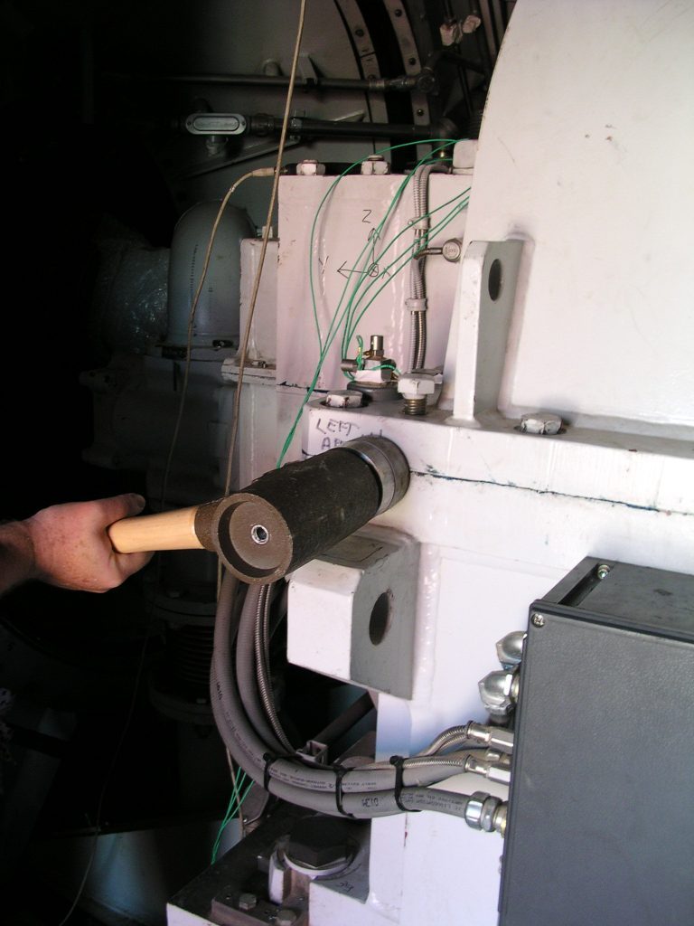
Stationary measurements (modal analysis)
Measurements are carried out by exciting the system with a force and measuring vibratory responses using sensors such as accelerometers. The data collected is then used to determine the system’s natural frequencies, modal shapes and damping.
Here are some important considerations when carrying out a modal analysis at standstill:
- Preparation: before starting measurements, it is important to ensure that the motor-fan is in good working order, and that all components are correctly installed and functioning properly. It is also important to ensure that all sensors are correctly installed and calibrated.
- Excitation: to perform a modal analysis, it is necessary to excite the system with a force. This force can be applied using a hammer or an electromechanical vibrator. It is important to ensure that the excitation is sufficient to generate a significant vibratory response, but not so high as to damage the system.
- Data acquisition: during data acquisition, it is important to ensure that the transducers are correctly positioned to measure system vibrations. It is also important to ensure that data is collected in real time, and that the sampling frequency is high enough to capture rapid variations in performance.
- Data analysis: once the data is collected, it is important to carry out an in-depth analysis to identify the system’s vibration modes. This can include spectral analysis to detect vibration frequencies, modal shape analysis to determine the system’s vibration shapes, and damping analysis to determine the system’s damping characteristics.